Background
The project used a syringe pump as a compact manufacturing challenge: the assembly combines a controlled linear motion, a rigid frame, and parts made through different processes.
The team had to coordinate 3D-printed parts with machined components while learning the strengths and limits of each process. The source also describes an intended MedWish distribution context that must be confirmed before launch.
Approach
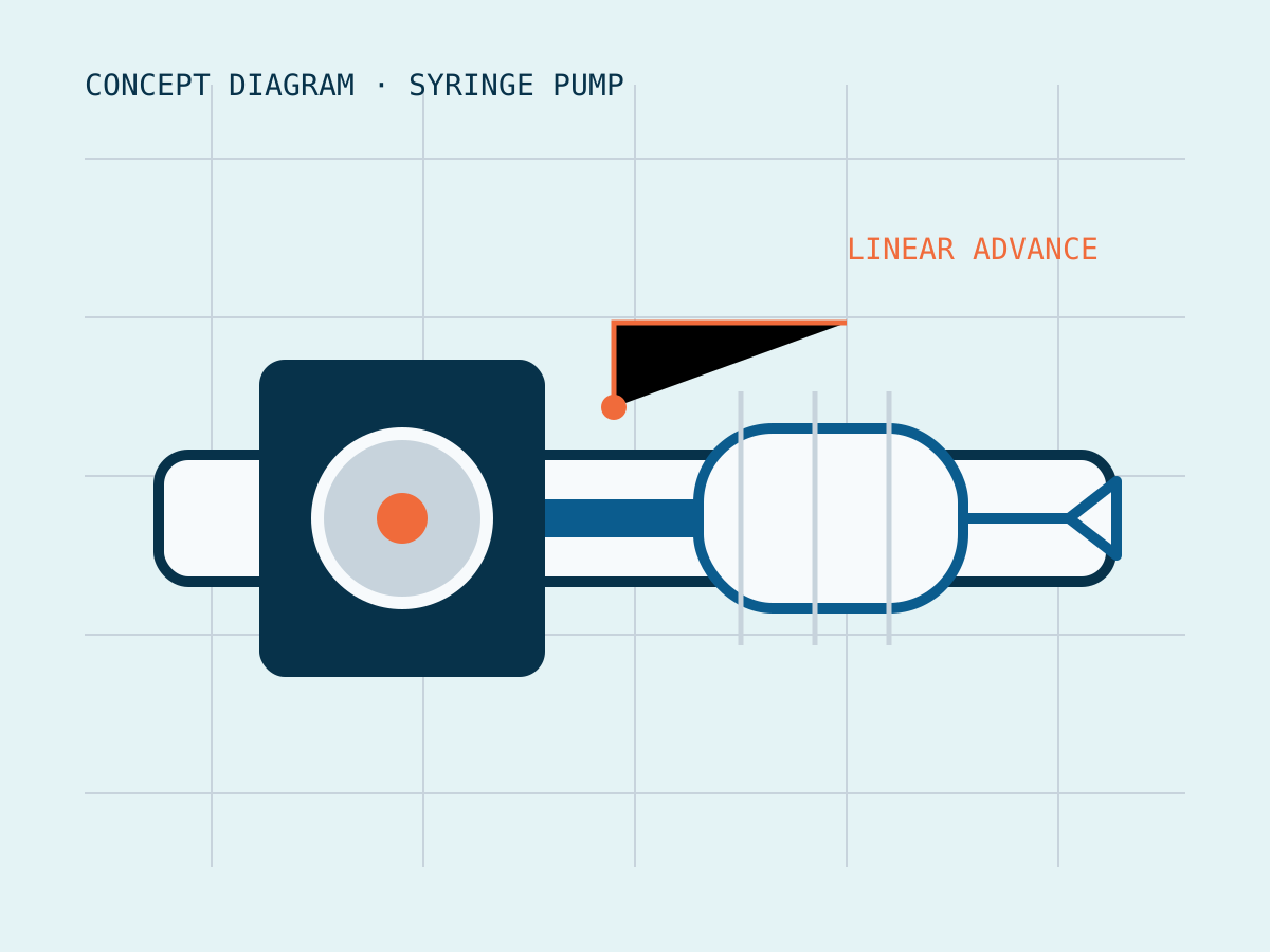
A syringe pump advances a plunger along a controlled linear path. This case study currently uses a clearly labeled concept diagram because no original project photography was available on the source site.
As a mechanical engineering lead, I participated in the 3D-printing workflow and recorded weekly meeting decisions. I also coordinated communication between the student team and CWRU MedWish leadership.
The work connected part preparation, fabrication, assembly planning, and team communication. Additional photographs and technical drawings are needed to document the actual build sequence in greater detail.
Impact
The project provided hands-on experience with additive manufacturing and the coordination required when printed and machined parts meet in one assembly. Current completion and distribution status still require confirmation.
Manufacturing projects expose interfaces that are easy to miss in a CAD-only workflow: tolerances, fixture access, assembly order, and the communication needed to keep each part compatible with the whole.